 Butch O'Hare Chapter, IPMS-USA
  Butch O'Hare Chapter, IPMS-USA
About 11 years ago, I decided to convert the ancient Testors Convair 440 into a turbo-prop Convair 580. This build required new engines and props, which led me into my first efforts at scratch building props as well as resin casting. After I developed some techniques, the task of scratch building props became less and less daunting. I also began to realize that my scratch built props were better looking than many of the 1/72nd and 1/144th kit props, and so I began building props for those kits as well. The process is a little tedious (especially for four engine aircraft), but if you give it a try, you may decide that the results are well worth the effort.
Materials
Prop hubs: Standard hubs as well as spinners
can be built using styrene rod or sprue. Chuck the rod/sprue into your rotary
tool, and shape using sandpaper. After getting the basic shape (dome or spinner),
polish the part with finer grit paper and polishing compound. Most standard
props consist of a domed forward section and a “stepped” or raised rear section
to which the prop blades are attached. This rear section can be made from
any number of materials: thin styrene tube, soda straws, and one of my favorites,
the sheathing from copper wire (the sheathing will stretch to fit over the
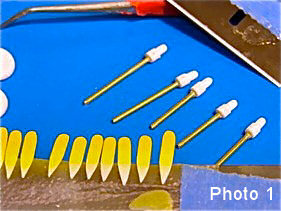
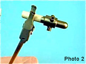
prop dome). Photo 1 shows prop hubs for a1/144th B-17, and photo 2 shows a
hub for a 1/72 A-26B. The hubs in both pictures are made from styrene rod,
with styrene tube used for the raised sections.
Note that in some cases, the prop hub or spinner in the kit is fine, but
the prop blades are clunky. In this case, cut off and replace the prop blades
(see next section).
Prop blades: Blade materials include .005 and .010 sheet styrene, and Mylar film, such as old floppy disc material. First, determine the blade length (using either the kit blades and/or reference material). Using the blade length as the width, cut a rectangular section of styrene/Mylar about 3-4 inches long. Next, make a pattern blade and super glue it perpendicular to a toothpick or piece of sprue. This will be used as a stencil to outline all of the blades on the rectangular section of styrene/Mylar. Hold the pattern blade over the styrene/Mylar, and with a pencil trace around the pattern. Keep repeating this until you have outlined as many blades as you need (always do a few extra, as there will be a few rejects in each batch). Next, using a small scissors (curved are best), cut out each blade.
Note that it is nearly impossible to cut the blade tips to the correct (curved) shapes. This is where sandpaper and tedium set in. I usually stack four to five of the rough-cut blades on top of one another, hold them tightly together, and then gently sand the tips to the correct shape.
Assembling the Props
Where and how to accurately position the prop blades around the hub (equal
spacing), caused me grief for a number of years, until I hit on this idea.
Cut a very thin piece of masking tape about 1/32nd to 1/16th of an inch wide
and 1-2 inches long. Mark one end of the tape with a small black dot, and
then wrap the tape around the hub/spinner one time. Where the tape overlaps
the first small black dot, place a second black dot, and then remove the tape.
The distance between the two dots is the circumference of the hub/spinner.
Lay the tape flat, and using a metric ruler, measure the distance between
the two dots.
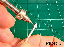
For example, say the distance is 12 millimeters. Depending on the number of prop blades (three, four or more), divide the distance (12 mm) by the number of blades. In our example, a 3 bladed prop would yield 12 mm divided by 3, or 4 mm. Now place small black dots at 4mm intervals on the 12 mm section of tape. The tape now has four dots on it, one at the end, the next at 4mm, the next at 8mm and the last one at 12 mm. Next, rewrap the tape around the hub/spinner one time, just as before. The first and last points overlap at the same point (point one). You now have three equally spaced points on the hub/spinner (point one, point two at 4 mm, and point three at 8 mm). Using a small needle probe, make a small “starter” hole in the hub/spinner at each of the three points. Remove the tape, and then use a small drill bit to enlarge the holes into which the prop blades will be inserted (see photo 3).
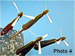
At this point, paint the blades and the hubs/spinners. After the paint dries,
attach the blades using Elmer's or Sobo white glue (see photo 4).